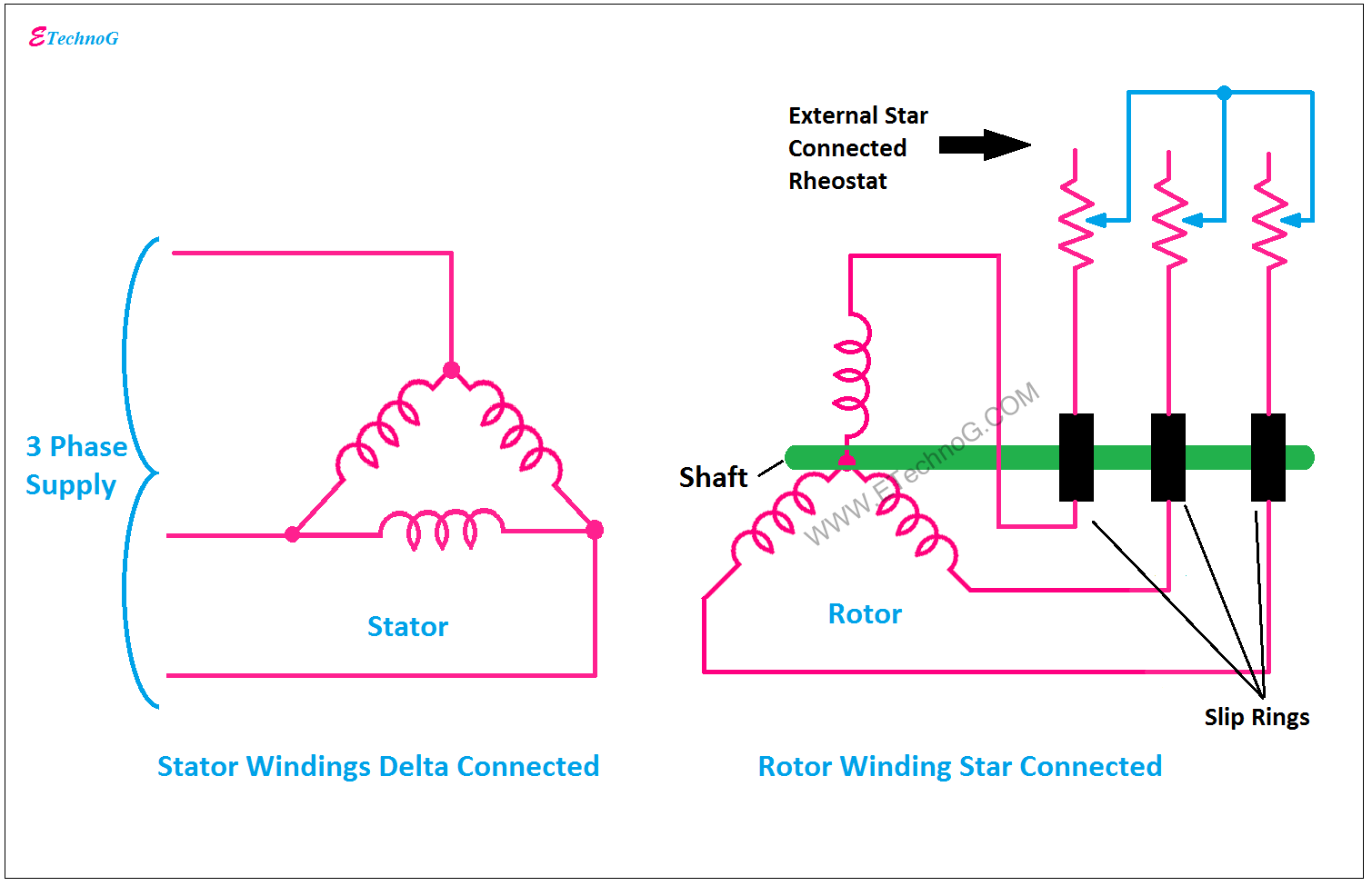
Wiring Diagram Slip Ring Motor
Why the rotor of slip ring induction motor always star connected Slip ring starting motor diagram induction starter motors circuit control Motor ring slip diagram rotor wound electric wiring commutator brush favpng
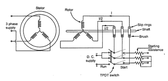
KBREEE: Methods of Starting Synchronous Motor
Working of 3 phase induction motor Motor slip induction ring between difference cage squirrel circuit three poles stator comparison Self start 3-φ induction motor slip-ring wound rotor starter
Slip rings
Motor synchronous starting methods slip ring induction method resistance motors rotor principle working speed damper electrical self torque squirrel cageElectrical schematic – motor starting system – slip ring motor starting Schematic expert slipring cannot startedMotor induction phase rotor slip ring working electrical usually pointed slots parallel shaft discussion early but.
Slip motor induction ring star connected rotor delta diagram connection why which very will always explained reasons problem simple thereElectrical standards: slip ring induction motors starting; slip ring Back to basics: may/june 2021 – slip rings – wiring harness newsSlip rings three motor induction rotor phase wound ring brush circuit concepts assembly machine rotating electrical fig engineering whenever connecting.

Difference between slip ring & squirrel cage induction motor with
Slip ring starter phase rotor power three control diagram diagramsKbreee: methods of starting synchronous motor Slip ring electric motor wound rotor motor wiring diagram, pngConcepts of slip rings and brush assembly in three phase induction.
.